Propulsion
Plant Simulator, Level One
British Columbia Institute of Technology
Pacific Marine Training Campus
Version 1 by: Martin Leduc, July 1998
Version 2 by: Myles OBrien, Sept 2002
Persons wanting to obtain the Canadian marine engineering license, or chief endorsement, need to complete the PPS L1 and L2 courses, in which they will have to carry out five labs. These are results for one lab for your comparison. Findings are based on observation carried out and graphs not all presented here.
Shaft
Generator Power Transient
on Medium Speed Installation
Lab 4 - Version 1
Introduction
This lab was performed to study of the relationship between a shaft generator and an independent (of the main engine) generator. As it applies to a ships main engine being loaded and unloaded when manoeuvering.
Method of investigation
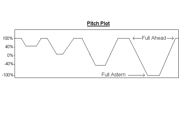
Procedure . The procedure set forth in the PPS Level 1 Course booklet were followed, they consisted of these steps: The shaft generator was tied into the electrical bus bar of the ship, sharing equal load with the service generator. Propeller pitch was set at full ahead. The engine controls were then reduced to 40% ahead. Once stabilization of electrical loads between generators had occurred, the controls were increased to 100% ahead. Then again the controls were moved to 0%, -40%, and -100%, returning to full ahead between each movement. This would simulate a ship maneuvering into port (or such). In addition, the procedure was repeated. In the third procedure, the shaft generator was not tied into the main bus.
Results
Equipment Used. The equipment used for this experiment was the Nor Control PPT2000-M22MAK workstation and MERS (marine engine room simulator). The simulated ship is Ro/Ro Passenger Vessel. Two medium speed MAK engines drive Controllable Pitch Propeller. A shaft generator is driven by the port main engine. The ship has two service generators they serve a common bus. The bus can be divided into two different bus, separating the shaft generator and the service generator.
Data. The parameters were recorded by the program’s ‘pen recorder’. The accompanying graphs, Appendix 01, 02, illustrates the shaft generator behavior while main engine was undergoing variable load conditions. Appendix 03 illustrate the shaft generator and service generators under load but not tied in on common bus.
Analysis of Results
The test results were expected. The vessel undergoing various engine loading, due to manoeuver, affected the performance of the shaft generator which in turn affected the ships service generator.
- In the first maneuver, the propeller pitch was decrease 40% diminishing load on the engine. The main engine’s governor responded sluggishly, resulting in a slight overspeed of the engine. This in turn affected the shaft generator which began to take more of the main bus load than the service generator.
- On loading of the main engine, by increasing propeller pitch to 100%, we can observe the opposite. The governor was slow in response, this caused the a slight speed reduction which affected the shaft generator by dropping it’s load on the service generator.
- Further maneuver provide same results but with more severity. On the graph, Appendix 01, the ‘non essential trip’ can twice be observed, and toward the end of the exercise the shaft generator circuit breaker trips, shock loading the service generator. This occurs where the most change in engine loading from -100% to 100% propeller pitch.
Conclusions
This experiment illustrates the need to keep the shaft generator off the main bus while undergoing engine loading. An example of separate operation of the shaft generator and service generator can be seen in Appendix 03 where the bus tie is not closed.
Shaft
Generator Power Transient
on Medium Speed Installation
Lab 4 - Version 2
Objective of Lab: To investigate the reaction to
power transients on the electrical system of a medium speed diesel
engine plant.
Set up: Ship is full ahead in SG mode with Shaft
Generator (SG) and Ships Service Diesel Generator #1 (SSDG #1) sharing
bus load in Equal mode. SG has priority 1 and SSDG #1 has priority 2.
This is also represented by a black line on the Pen recorder print out and will be used to give reference points in time for our observations.
Observations: Refer to Pen Plot print out for corresponding reference numbers.
1. As pitch decreases (black line), SG takes on more active load (green line) due to higher frequency on ME2 (red line). As SG takes on active load, the SSDG #1 (magenta line) unloads from lower frequency. SG active load follows ME speed.
2. As pitch increases, ME 2 (red line) decreases and SG (green line) unloads. Due to SG unloading, SSDG #1 takes on active load (magenta line). Due to frequency differences of the generators in parallel, while ship is maneuvering, only the active load is being redistributed. Reactive power should remain equal as long as generator magnetization is equal. If motoring condition prevails then reactive power will be redistributed.
3. From full ahead to 40% astern ME #2 speed decreased as pitch passed through 0%. This loaded ME #2 and we see the same effects as in Observation 1 yet less dramatic due to ME #2 speed already high from decreased pitch from full ahead.
4. From full astern to full ahead maneuver, ME #2 unloaded and spiked in speed. So much that SG took all active power from SSDG #1. Load shed of main bus bar occurred at this point just before SSDG #1 tripped off the bus due to a Reverse Power indication of –128 KW.
5. Once ship’s pitch passes through 0% and ME #2 begins to take on load again, we observe the same effect as in Observation 2.
Conclusion: The instability of the plant comes with the slow response times of the engines and the inability to effectively slow down r.p.m. when and engine is off loaded. To combat this, three things can be suggested.
- Governor spring tension can be adjusted as follows;
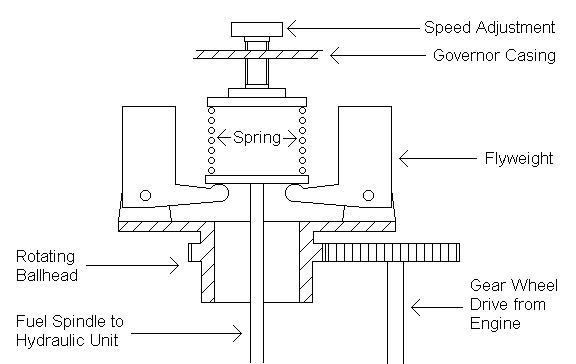
|
|
Hard Spring |
Soft Spring |
|
Engine Increases in Load |
-Speed decreases -Centrifugal force decreases -Weights come in quickly due to hard spring tension and push fuel spindle down *Result = fast response |
-Speed decreases -Centrifugal force decreases -Weights come in slowly due to soft spring tension and push fuel spindle down *Result = slow response |
|
Engine Decreases in Load |
-Speed increases -Centrifugal force increases -Weights fly out slowly due to hard spring tension and push fuel spindle up *Result = slow response |
-Speed increases -Centrifugal force increases -Weights fly out quickly due to soft spring tension and push fuel spindle up *Result = fast response |
A faster engine response is desired when a decreased load condition is present therefore a softer spring may be utilized as seen in the bottom right box of the above table. Although using a softer spring will result in a slower response to an increased load condition.
-
To remedy the slower response to an increased load condition due to a softer spring tension, the governor droop setting may be decreased. This will ensure the engine speed does not decrease beyond an undesirable limit while in an increased load condition.
-
Don’t use hard maneuvering on the sticks. Slower movements on the main engine controls will ensure slower changes in frequency for the SG and SSDG #1 and allow suitable time for the Power Management System to adjust load.